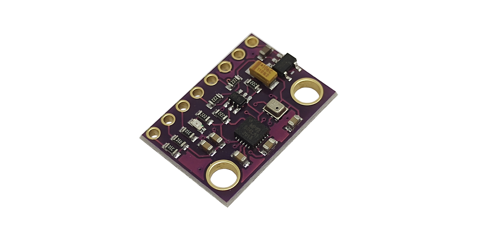
MPU9250-BMP280 consiste em um módulo GY-91 altamente versátil. É equipado com os sensores Invensense MPU9250 e Bosch BMP280 em uma única placa, fornecendo 10 graus de liberdade (10DOF) no total.
O MPU9250 é um módulo de dispositivo de rastreamento de movimento de 9 eixos multi-chip que consiste em um giroscópio de 3 eixos, um acelerômetro de 3 eixos e um magnetômetro de 3 eixos AK8963 além de um sensor de temperatura integrado.
O BMP280 é um sensor de pressão barométrica absoluta especialmente projetado para aplicações móveis. Também é equipado com seu próprio sensor de temperatura assim como o que acompanha o MPU9250.
Funcionamento
MPU9250 e BMP280 compartilham o mesmo barramento de comunicação I2C. A integração com o Arduino no nível do software é muito simples, pois existem bibliotecas prontas para serem usadas. No nível de hardware, o módulo inclui um regulador de 3,3 V na placa, bem como resistores pull-up no barramento I2C.
Como sucessor do amplamente adotado BMP180, o BMP280 oferece alto desempenho em todas as aplicações que requerem medição precisa de pressão. O BMP280 opera com ruído mais baixo, suporta novos modos de filtro, tem a vantagem sobre o BMP180 de ser 63% menor e 13% mais veloz. A comunicação do BMP280 com o dispositivo é realizada usando I2C a 400kHz compartilhada com MPU9250 ou SPI a 1MHz.
Especificações Técnicas MPU9250-BMP280
-
- Módulo GY-91: MPU9250 + BMP280
- Tensão de funcionamento: 3V / 3.3V ~ 5V DC
- Interface de comunicação: I2C e SPI
- Comunicação compatível com 3.3V ou 5V
Sensor: MPU9250
-
- Faixa do acelerômetro: ± 2g, ± 4g, ± 8g, ± 16g
- Gama do giroscópio: ± 250Grad / seg, ± 500Grad / Sec, ± 1000Grad / seg, ± 2000Grad / Sec
- Faixa do magnetômetro: ± 4800µT
- Conversor AD: 16 bits (saída digital)
- Graus de liberdade (DOF): 9
Sensor: BMP280
-
- Faixa de Pressão: 300 a 1100 hPa
- Resolução: 0,16 Pa
- Precisão absoluta: 1 hPa
- Medição de temperatura incluída
- Resolução de temperatura: 0,01 °C
- Precisão Temperatura: 1 °C
- Frequência de amostragem: 157 Hz (máx.)
- Regulador de tensão integrado na placa
- Consumo de energia ultrabaixo
- Completamente calibrado
- Dimensões: 2,5 cm x 1,4 cm x 0,3 cm
Pinagem
-
- VIN: tensão de alimentação 5V
- 3V3: saída de 3,3V
- GND: terra 0V
- SCL: Clock I2C / Clock SPI
- SDA: entrada de dados I2C Data / SPI
- SDO / SAO: Saída de dados SPI / I2C Pino de configuração do endereço escravo
- NCS: Chip Select para o modo SPI apenas para MPU-9250
- CSB: Chip Select para BMP280
Simples projeto
A obtenção de dados do sensor será mostrado de forma simples e direta.
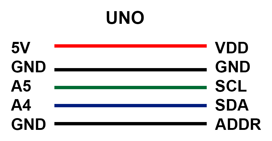
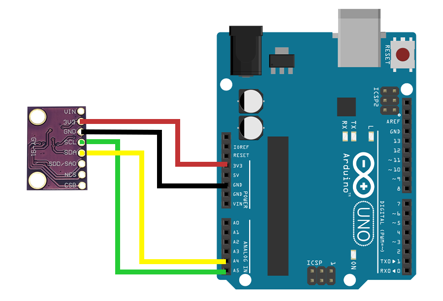
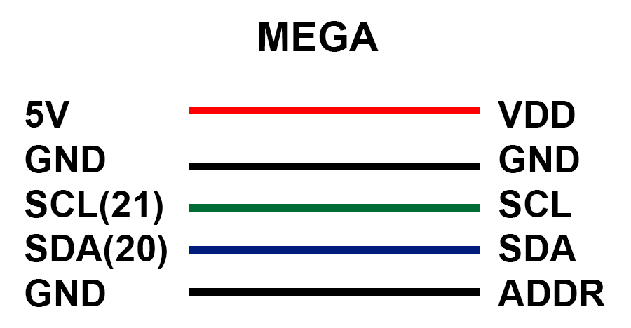
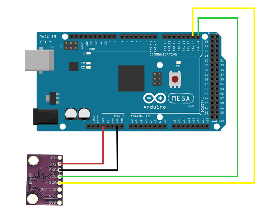
Conexão do Sensor MPU9250-BMP280 com Arduino
A conexão com o Arduino é muito simples, siga conforme o esquema abaixo:
Código
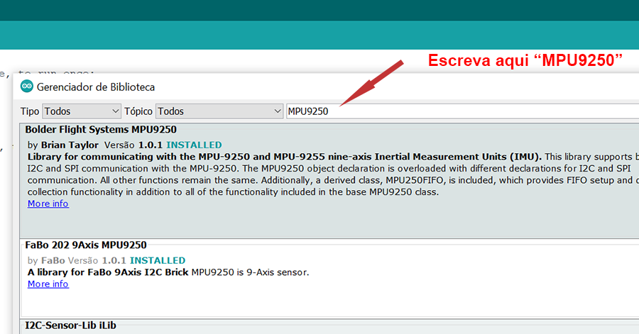
Primeiramente, devemos incluir as bibliotecas MPU9250 e BMP280. Em seguida, baixe o código para fazermos o experimento com o sensor.
OBS: Talvez seja necessário atualizar as bibliotecas. Então, sugiro atualizar todas pelo Gerenciador de Bibliotecas.

Calibração do MPU9250-BMP280
Feita a atualização das bibliotecas, inicialmente devemos obter os parâmetros de calibração para ser usado definitivamente no sensor.
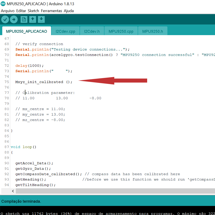
Com o código já aberto, verifique se a função “Mxyz_init_calibrated ( )” está ativa para se iniciar o processo de calibração.
Sugestão: adquira um cabo USB com um tamanho suficiente para permitir diversos giros, um cabo de uma impressora atende muito bem.
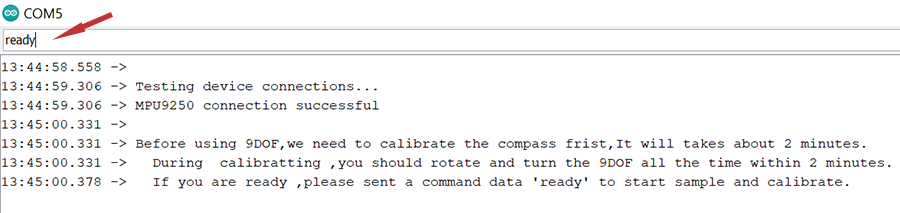
Então, carregue o código no Arduino, verifique a velocidade no Monitor Serial e aguarde o reconhecimento do sensor.
#include "Wire.h"

// I2Cdev and MPU9250 must be installed as libraries, or else the .cpp/.h files
// for both classes must be in the include path of your project
#include "I2Cdev.h"
#include "MPU9250.h"

// class default I2C address is 0x68
// specific I2C addresses may be passed as a parameter here
// AD0 low = 0x68 (default for InvenSense evaluation board)
// AD0 high = 0x69
MPU9250 accelgyro;
I2Cdev   I2C_M;

uint8_t buffer_m[6];

int16_t ax, ay, az;
int16_t gx, gy, gz;
int16_t mx, my, mz;

float heading;
float tiltheading;

float Axyz[3];
float Gxyz[3];
float Mxyz[3];

#define sample_num_mdate  5000

volatile float mx_sample[3];
volatile float my_sample[3];
volatile float mz_sample[3];

static float mx_centre = 0;
static float my_centre = 0;
static float mz_centre = 0;

volatile int mx_max = 0;
volatile int my_max = 0;
volatile int mz_max = 0;

volatile int mx_min = 0;
volatile int my_min = 0;
volatile int mz_min = 0;

float temperature;
float pressure;
float atm;
float altitude;

void setup()
{
  // join I2C bus (I2Cdev library doesn't do this automatically)
  Wire.begin();

  // initialize serial communication
  // (38400 chosen because it works as well at 8MHz as it does at 16MHz, but
  // it's really up to you depending on your project)
  //Serial.begin(38400);

  Serial.begin(38400);

  // initialize device
  Serial.println("Initializing I2C devices...");
  accelgyro.initialize();

  // verify connection
  Serial.println("Testing device connections...");
  Serial.println(accelgyro.testConnection() ? "MPU9250 connection successful" : "MPU9250 connection failed");

  delay(1000);
  Serial.println("     ");

  // Mxyz_init_calibrated ();

  // Calibration parameter:
  // 11.00         12.00         -7.00

  mx_centre = 11.00;
  my_centre = 12.00;
  mz_centre = -7.00;

}


void loop()
{

  getAccel_Data();
  getGyro_Data();
  getCompassDate_calibrated(); // compass data has been calibrated here
  getHeading();               //before we use this function we should run 'getCompassDate_calibrated()' frist, so that we can get calibrated data ,then we can get correct angle .
  getTiltHeading();

  Serial.println("calibration parameter: ");
  Serial.print(mx_centre);
  Serial.print("         ");
  Serial.print(my_centre);
  Serial.print("         ");
  Serial.println(mz_centre);
  Serial.println("     ");


  Serial.println("Acceleration(g) of X,Y,Z:");
  Serial.print(Axyz[0]);
  Serial.print(",");
  Serial.print(Axyz[1]);
  Serial.print(",");
  Serial.println(Axyz[2]);
  Serial.println("Gyro(degress/s) of X,Y,Z:");
  Serial.print(Gxyz[0]);
  Serial.print(",");
  Serial.print(Gxyz[1]);
  Serial.print(",");
  Serial.println(Gxyz[2]);
  Serial.println("Compass Value of X,Y,Z:");
  Serial.print(Mxyz[0]);
  Serial.print(",");
  Serial.print(Mxyz[1]);
  Serial.print(",");
  Serial.println(Mxyz[2]);
  Serial.println("The clockwise angle between the magnetic north and X-Axis:");
  Serial.print(heading);
  Serial.println(" ");
  Serial.println("The clockwise angle between the magnetic north and the projection of the positive X-Axis in the horizontal plane:");
  Serial.println(tiltheading);
  Serial.println("   ");
  Serial.println();

  delay(1000);

}


void getHeading(void)
{
  heading = 180 * atan2(Mxyz[1], Mxyz[0]) / PI;
  if (heading < 0) heading += 360;
}

void getTiltHeading(void)
{
  float pitch = asin(-Axyz[0]);
  float roll = asin(Axyz[1] / cos(pitch));

  float xh = Mxyz[0] * cos(pitch) + Mxyz[2] * sin(pitch);
  float yh = Mxyz[0] * sin(roll) * sin(pitch) + Mxyz[1] * cos(roll) - Mxyz[2] * sin(roll) * cos(pitch);
  float zh = -Mxyz[0] * cos(roll) * sin(pitch) + Mxyz[1] * sin(roll) + Mxyz[2] * cos(roll) * cos(pitch);
  tiltheading = 180 * atan2(yh, xh) / PI;
  if (yh < 0)    tiltheading += 360;
}


void Mxyz_init_calibrated ()
{

  Serial.println(F("Before using 9DOF,we need to calibrate the compass frist,It will takes about 2 minutes."));
  Serial.print("  ");
  Serial.println(F("During  calibratting ,you should rotate and turn the 9DOF all the time within 2 minutes."));
  Serial.print("  ");
  Serial.println(F("If you are ready ,please sent a command data 'ready' to start sample and calibrate."));
  while (!Serial.find("ready"));
  Serial.println("  ");
  Serial.println("ready");
  Serial.println("Sample starting......");
  Serial.println("waiting ......");

  get_calibration_Data ();

  Serial.println("     ");
  Serial.println("compass calibration parameter ");
  Serial.print(mx_centre);
  Serial.print("     ");
  Serial.print(my_centre);
  Serial.print("     ");
  Serial.println(mz_centre);
  Serial.println("    ");
}


void get_calibration_Data ()
{
  for (int i = 0; i < sample_num_mdate; i++)
  {
    get_one_sample_date_mxyz();
    /*
      Serial.print(mx_sample[2]);
      Serial.print(" ");
      Serial.print(my_sample[2]);                            //you can see the sample data here .
      Serial.print(" ");
      Serial.println(mz_sample[2]);
    */

    if (mx_sample[2] >= mx_sample[1])mx_sample[1] = mx_sample[2];
    if (my_sample[2] >= my_sample[1])my_sample[1] = my_sample[2]; //find max value
    if (mz_sample[2] >= mz_sample[1])mz_sample[1] = mz_sample[2];

    if (mx_sample[2] <= mx_sample[0])mx_sample[0] = mx_sample[2];
    if (my_sample[2] <= my_sample[0])my_sample[0] = my_sample[2]; //find min value
    if (mz_sample[2] <= mz_sample[0])mz_sample[0] = mz_sample[2];

  }

  mx_max = mx_sample[1];
  my_max = my_sample[1];
  mz_max = mz_sample[1];

  mx_min = mx_sample[0];
  my_min = my_sample[0];
  mz_min = mz_sample[0];

  mx_centre = (mx_max + mx_min) / 2;
  my_centre = (my_max + my_min) / 2;
  mz_centre = (mz_max + mz_min) / 2;

}


void get_one_sample_date_mxyz()
{
  getCompass_Data();
  mx_sample[2] = Mxyz[0];
  my_sample[2] = Mxyz[1];
  mz_sample[2] = Mxyz[2];
}


void getAccel_Data(void)
{
  accelgyro.getMotion9(&ax, &ay, &az, &gx, &gy, &gz, &mx, &my, &mz);
  Axyz[0] = (double) ax / 16384;
  Axyz[1] = (double) ay / 16384;
  Axyz[2] = (double) az / 16384;
}


void getGyro_Data(void)
{
  accelgyro.getMotion9(&ax, &ay, &az, &gx, &gy, &gz, &mx, &my, &mz);

  Gxyz[0] = (double) gx * 250 / 32768;
  Gxyz[1] = (double) gy * 250 / 32768;
  Gxyz[2] = (double) gz * 250 / 32768;
}


void getCompass_Data(void)
{
  I2C_M.writeByte(MPU9150_RA_MAG_ADDRESS, 0x0A, 0x01); //enable the magnetometer
  delay(10);
  I2C_M.readBytes(MPU9150_RA_MAG_ADDRESS, MPU9150_RA_MAG_XOUT_L, 6, buffer_m);

  mx = ((int16_t)(buffer_m[1]) << 8) | buffer_m[0] ;
  my = ((int16_t)(buffer_m[3]) << 8) | buffer_m[2] ;
  mz = ((int16_t)(buffer_m[5]) << 8) | buffer_m[4] ;

  Mxyz[0] = (double) mx * 1200 / 4096;
  Mxyz[1] = (double) my * 1200 / 4096;
  Mxyz[2] = (double) mz * 1200 / 4096;
}

void getCompassDate_calibrated ()
{
  getCompass_Data();
  Mxyz[0] = Mxyz[0] - mx_centre;
  Mxyz[1] = Mxyz[1] - my_centre;
  Mxyz[2] = Mxyz[2] - mz_centre;
}
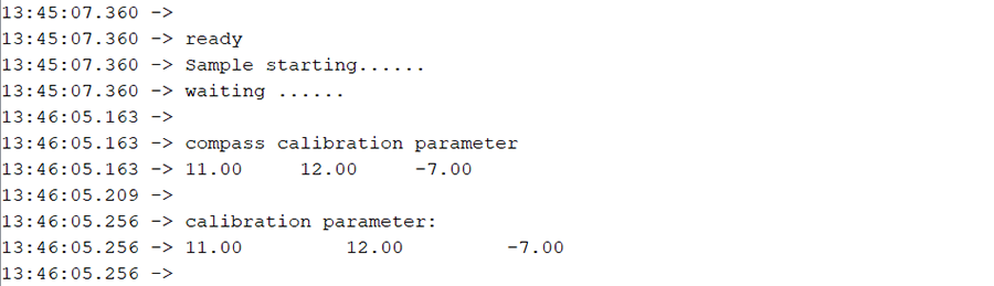
Feito isso, execute o comando “ready”, gire e movimente o sensor até aparecer os parâmetros de calibração.
Funcionamento do MPU9250-BMP280
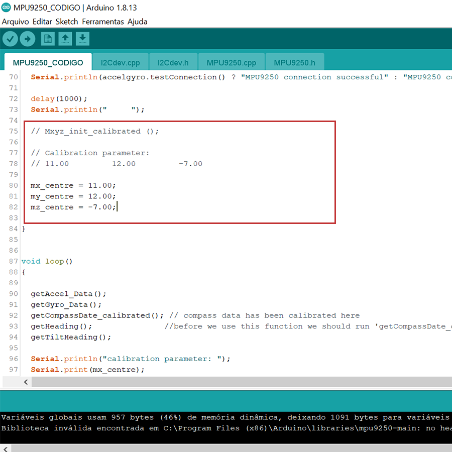
Então, copie parâmetros obtidos anteriormente e insira no código com as alterações.
Agora, carregue o código novamente e abra o Monitor Serial.

Vejam os valores apresentados do acelerômetro, giroscópio, magnetômetro e também da proa e da inclinação da proa em relação ao eixo X.
Então, percebe-se que com esse código é possível criar uma grande gama de projetos.
Aplicação com BMP280
Nesse sensor está incluído um barômetro BMP280 que com a aplicação a seguir será possível observar o seu funcionamento.
Então, inclua a biblioteca BMx280I2C.h e carregue o código.
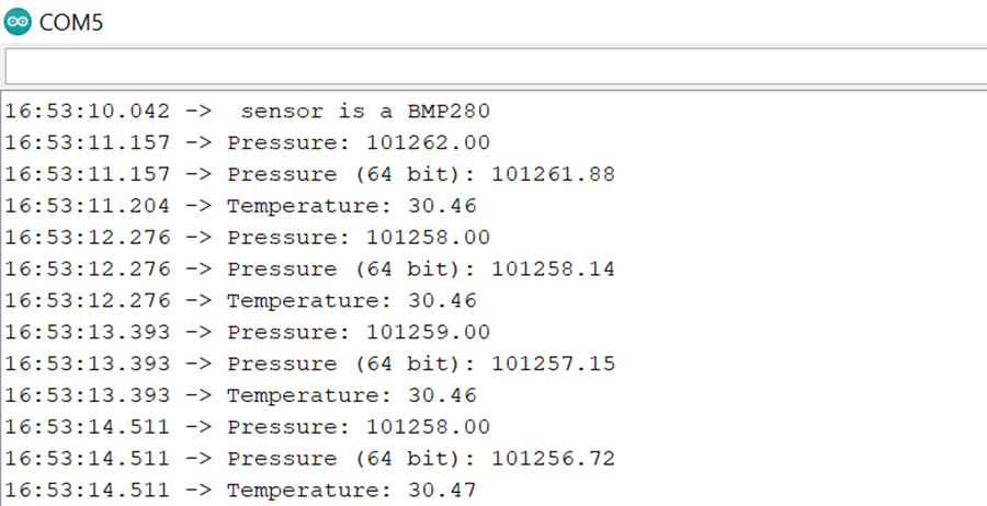
// BMx280_I2C.ino
//
// shows how to use the BMP280 / BMx280 library with the sensor connected using I2C.
//
// Copyright (c) 2018 Gregor Christandl
//
// connect the AS3935 to the Arduino like this:
//
// Arduino - BMP280 / BME280
// 3.3V ---- VCC
// GND ----- GND
// SDA ----- SDA
// SCL ----- SCL
// some BMP280/BME280 modules break out the CSB and SDO pins as well:
// 5V ------ CSB (enables the I2C interface)
// GND ----- SDO (I2C Address 0x76)
// 5V ------ SDO (I2C Address 0x77)
// other pins can be left unconnected.

#include <Arduino.h>
#include <Wire.h>

#include <BMx280I2C.h>

#define I2C_ADDRESS 0x76

//create a BMx280I2C object using the I2C interface with I2C Address 0x76
BMx280I2C bmx280(I2C_ADDRESS);

void setup() {
  // put your setup code here, to run once:
	Serial.begin(38400);

	//wait for serial connection to open (only necessary on some boards)
	while (!Serial);

	Wire.begin();

	//begin() checks the Interface, reads the sensor ID (to differentiate between BMP280 and BME280)
	//and reads compensation parameters.
	if (!bmx280.begin())
	{
		Serial.println("begin() failed. check your BMx280 Interface and I2C Address.");
		while (1);
	}

	if (bmx280.isBME280())
		Serial.println("sensor is a BME280");
	else
		Serial.println("sensor is a BMP280");

	//reset sensor to default parameters.
	bmx280.resetToDefaults();

	//by default sensing is disabled and must be enabled by setting a non-zero
	//oversampling setting.
	//set an oversampling setting for pressure and temperature measurements.
	bmx280.writeOversamplingPressure(BMx280MI::OSRS_P_x16);
	bmx280.writeOversamplingTemperature(BMx280MI::OSRS_T_x16);

	//if sensor is a BME280, set an oversampling setting for humidity measurements.
	if (bmx280.isBME280())
		bmx280.writeOversamplingHumidity(BMx280MI::OSRS_H_x16);
}

void loop() {
  // put your main code here, to run repeatedly:

	delay(1000);

	//start a measurement
	if (!bmx280.measure())
	{
		Serial.println("could not start measurement, is a measurement already running?");
		return;
	}

	//wait for the measurement to finish
	do
	{
		delay(100);
	} while (!bmx280.hasValue());

	Serial.print("Pressure: "); Serial.println(bmx280.getPressure());
	Serial.print("Pressure (64 bit): "); Serial.println(bmx280.getPressure64());
	Serial.print("Temperature: "); Serial.println(bmx280.getTemperature());

	//important: measurement data is read from the sensor in function hasValue() only.
	//make sure to call get*() functions only after hasValue() has returned true.
	if (bmx280.isBME280())
	{
		Serial.print("Humidity: ");
		Serial.println(bmx280.getHumidity());
	}
}
Então, abra o Monitor Serial e observe as leituras da temperatura e pressão atmosférica.